Connectors may be very basic components that many people do not give much thought to. However, there are now so many different styles of connector it can be useful to know some of the terminology used. This can not only help navigate the different connectors on offer but also help you identify the best connector for the job.
Back to basics
A connector is an electromechanical device used for joining two electrical parts, usually, this would be connecting a cable to a system or cable to another cable within an electrical circuit. There are many different types of connectors which can achieve this and knowing the general terminology can go a long way to choosing the correct style of connector for your requirements.
| Male | The male part of a connector is called the plug, this generally includes the pin contacts for the connection. |
| Female | The female part of the connector is called the socket, this generally holds the contact sockets where the male pins insert to create the connection. The female side is commonly the live side of the connection as the contact sockets are more difficult to touch making the connection safer. |
| Jack | Some connectors may also be referred to as a jack, this is the female part of a connection that is installed on the surface on an encloser. Common jack connections are RJ45 (ethernet), telephone and audio (RCA) jack connectors. |
| Jack Plug | The male part of a jack connection is still a plug and is often called a jack plug to differentiate it with other plug connections. |
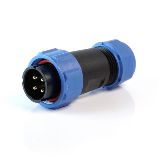
| Inline/Cable | An inline or cable connection describes a connector used to connect one cable to another. These are usually in a straight line but can also be 90° connectors. |
| Chassis/Panel | A panel-mounted connector is one that is designed to be installed onto a panel or enclosure. These are available in different mounting options and are a secure way of bringing wiring into a product. |
| PCB Mount | As the name suggests these are connectors where the socket is soldered directly onto a PCB board.
|
| Splice/Butt Connectors | These connectors permanently join two wires or cables together, they are usually smaller than standard connectors do to their non-mating design. |
| Circular Connectors | These are a very standard style of connector with many different options. They have a circular shell which means they can utilise many different mating styles. They can also be produced with high levels of waterproofing and higher robustness compared to other styles of connector. |
| Hybrid Connectors | These connectors can safely carry a mix of both power and signal circuits so are ideal for saving space or mitigating potential wiring issues. Hybrid connectors can also carry a mix of electronic and non-electronic circuits such as a signal circuit mixed with a pneumatic or optical signal circuit.
|
| IP Rating | The IP rating system is a universally recognised system for describing the ingress protection against physical objects and moisture. To learn more about this check out our guide here. |
| Filter Connector | A filtered connector is specially designed to allow signals to pass through uninterrupted while limiting the amount of EMI (electromagnetic interference) entering or exiting the product. To find out more about EMI check out our guide here.
|
| Pins/Contacts | The pin or contact of a connector refers to the metal pins inside which make the electrical connection and complete the circuit. |
| Pin/Contact Number | This is the number of electrical contacts within the connector. |
| Pin/Connector Size | This is the diameter of the electrical contact within the connector. This also directly relates to the amount of current the connector can handle. |
| Pin Layout/Contact Arrangement | This relates to the design of the electrical contacts including the spacing between the contacts and their layout. This means other connectors even with the same contact number will not fit always fit the connector as the contacts will not line up.
|
| Shell/Backshell | The shell is the body of the connector, this provides the ability to mate the connectors. It also offers the electrical insulation, EMI protection and the connectors robustness and weather sealing properties. |
| Shell Size | This is the dimensions of the shell. The size is usually the diameter of the connector but it can also be the panel cut out size or the full dimensions of the connector depending on the manufacturer. |
| Keyway | A keyway is designed to only allow a matching connector to mate. This is made up of one or more small protrusions with a specific placement on one side of the connection while the mating connector has cutouts of the same size and placement. This allows these connectors to fit together and reduces the chance of mating the wrong connectors. |
| Bayonet Coupling | This is a style of mating where you push the connectors together and then part turn a locking nut which fixes the connectors together. The benefit of this is that is it a solid connection which is quicker to connect and disconnect when compared with screw style mating. |
| Screw Coupling | This style of mating is where the connectors are pushed together and then a locking nut is screwed into position on the mating connector. This style of connector takes longer to connect but gives the most solid style of connection and can offer higher IP ratings. |
| Push-Pull Coupling | A push-pull connector is mated together by lining up the keyway or contacts and then pushing the two connectors together until you hear and feel a positive click. To separate the connectors you push the connectors together while pulling the locking nut away from the mating connector. This releases the connection and the connectors can be pulled apart. |
| Snap-In Coupling | This style of connector is held in place by friction. Once the keyway has been lined up you push the connector together until you hear and feel a click. To disconnect these you simply pull the connectors apart. |
| Magnetic Coupling | Magnetic mating connectors use a magnetic force to hold the connectors together. These have the added advantage of being easily disconnected which means they are ideal for applications where a machine needs to be moved quickly or accidental damage to the connectors could occur such as in medical devices. |
| Plating | Plating is the process of adding a thin layer of material to a different material. This can be seen on both the shell and contacts of a connector. The contacts are often made of a highly conductive metal this can then be gold plated to offer better transmission of extra-low voltage signals. The connectors shell can also be plated which can be for protection or aesthetic purposes, such as nickel plating to give a better look to the connector. |
| Rear Potted | Rear potting is the final sealing at the back of a panel mount connector, this is done to prevent water ingress to an enclosure even if the connector itself is not covered. |
| O-ring | An O-ring is a sealing ring that fits around the edge of a connector, this gives the connector a high amount of protection again water ingress. |
| Termination Style | This relates to the way in which the connector contact is attached to the electronic wires of the circuit. |
| Crimp | Crimp terminations use a crimping tool to compress the contact material onto a wire thereby holding it in place. These can be used on very small contacts and are generally quicker than soldering. |
| Solder | Soldering is where solder wire is melted into a bucket on the contact and the wire of the electronic circuit is melted (soldered) to the contact. This offers a very strong and reliable connection but generally takes longer than crimping. |
| Screw | This is a very basic and easy way of connecting wires to a connector. A wire is placed into a pre-made opening on a contact and a screw is then tightened to hold the wire in place. The benefit of this is the ease of installation and the ability to easily disconnect the wire in the future. Screw terminations are only available on some connectors due to the size on the contacts prohibiting their use. |
| Back/Rear Mounted | This relates to how the connector is mounted to a panel or enclosure. With back mounting the connector is installed from behind the panel with the mounting flange sitting inside the panel and the locking nut being on the outside.
|
| Front Mounted | This relates to how the connector is mounted to a panel or enclosure. With front mounting, the connector is installed from the front of the panel with the mounting flange sitting outside of the panel and the locking nut being on the inside. This style of mounting often gives a flush finish to a panel which is useful in applications requiring cleaning or for aesthetic reasons. |
